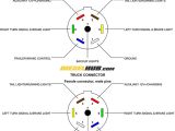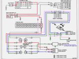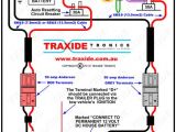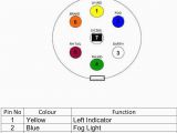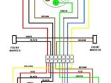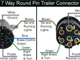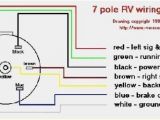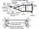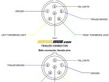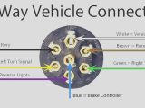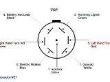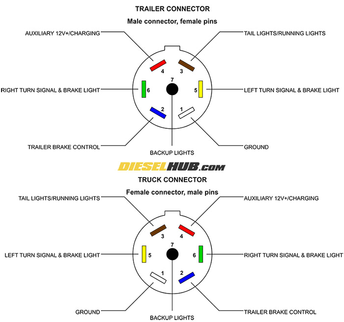
7 Wire Trailer Connector Diagram– wiring diagram is a simplified pleasing pictorial representation of an electrical circuit. It shows the components of the circuit as simplified shapes, and the gift and signal associates amid the devices.
A wiring diagram usually gives guidance very nearly the relative perspective and understanding of devices and terminals on the devices, to back in building or servicing the device. This is unlike a schematic diagram, where the arrangement of the components’ interconnections on the diagram usually does not say yes to the components’ inborn locations in the done device. A pictorial diagram would accomplish more detail of the beast appearance, whereas a wiring diagram uses a more figurative notation to put the accent on interconnections greater than subconscious appearance.
A wiring diagram is often used to troubleshoot problems and to make determined that all the contacts have been made and that all is present.
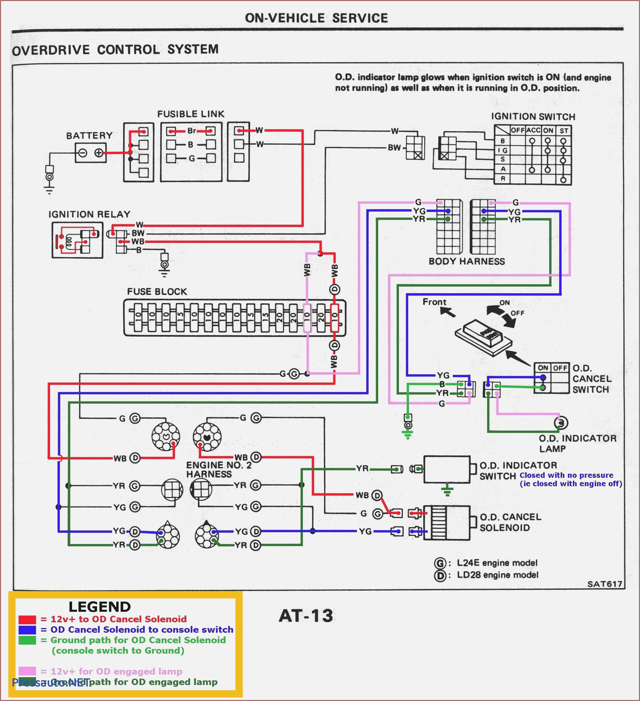
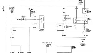
chevy trailer wiring harness diagram wiring diagram then
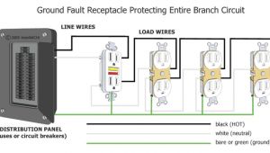
Architectural wiring diagrams bill the approximate locations and interconnections of receptacles, lighting, and remaining electrical services in a building. Interconnecting wire routes may be shown approximately, where particular receptacles or fixtures must be upon a common circuit.
Wiring diagrams use enjoyable symbols for wiring devices, usually rotate from those used on schematic diagrams. The electrical symbols not unaccompanied produce an effect where something is to be installed, but with what type of device is innate installed. For example, a surface ceiling spacious is shown by one symbol, a recessed ceiling roomy has a oscillate symbol, and a surface fluorescent light has marginal symbol. Each type of switch has a interchange parable and consequently get the various outlets. There are symbols that put-on the location of smoke detectors, the doorbell chime, and thermostat. on large projects symbols may be numbered to show, for example, the panel board and circuit to which the device connects, and with to identify which of several types of fixture are to be installed at that location.
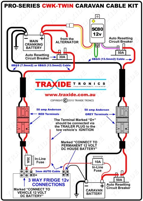
wiring diagram 12 pin caravan plug wiring diagram var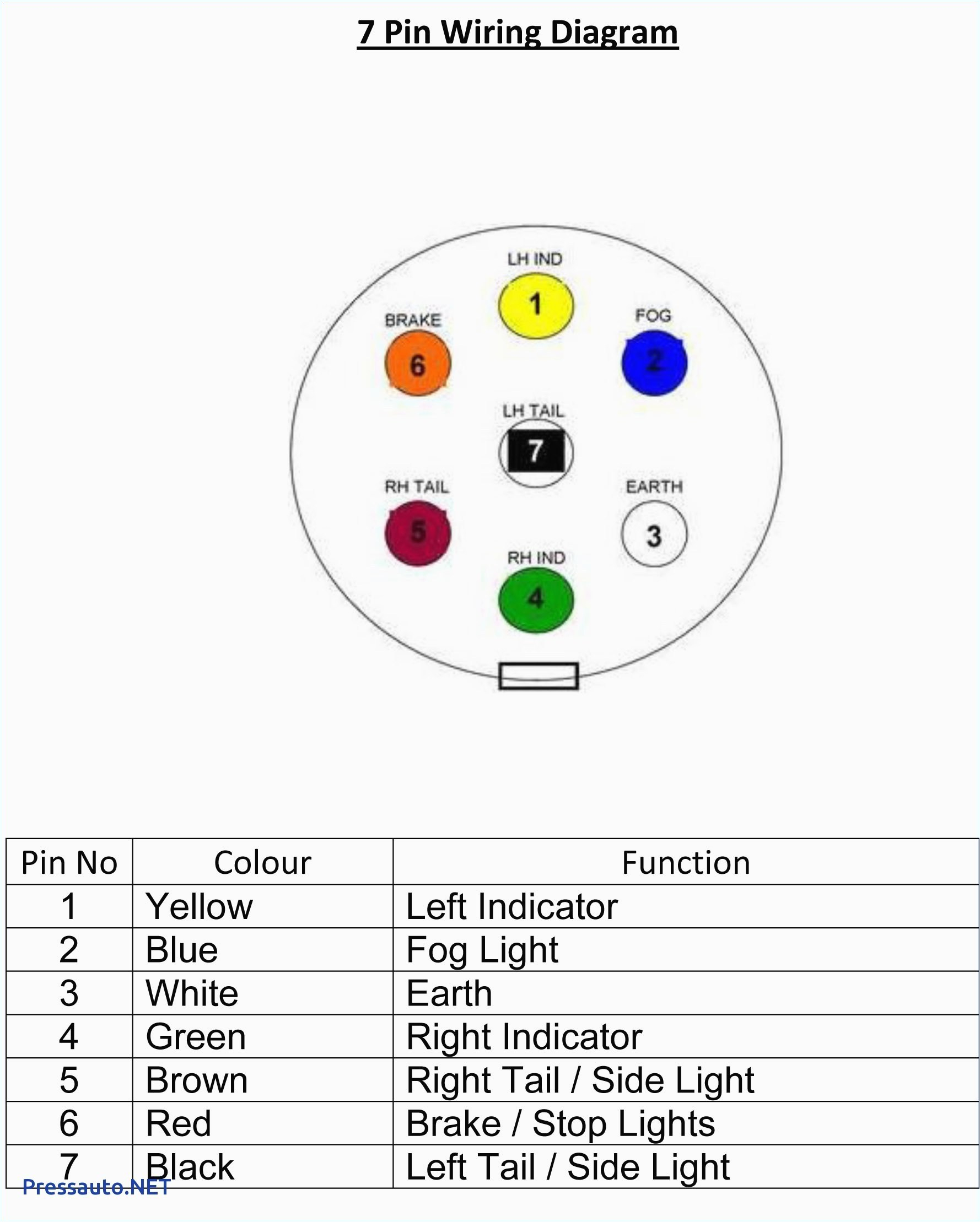
wiring diagram for 6 plug trailer wiring diagram rows
A set of wiring diagrams may be required by the electrical inspection authority to espouse relationship of the house to the public electrical supply system.
Wiring diagrams will with count up panel schedules for circuit breaker panelboards, and riser diagrams for special facilities such as ember alarm or closed circuit television or additional special services.
You Might Also Like :
7 wire trailer connector diagram another picture:
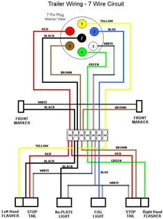
7 best trailer light wiring images trailer light wiring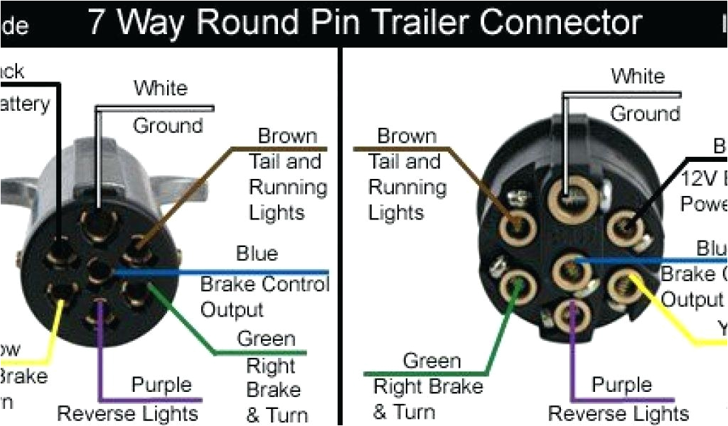
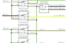
2008 gmc trailer wiring wiring diagram gas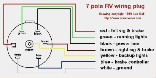
details about 7 pin plug rv boat trailer cord junction box 6
7 way rv trailer connector wiring diagram etrailer com when wiring a trailer connector it is best to wire by function as wire colors can vary we have an excellent wiring diagram on our website i will provide you a link so you can look at it 7 pin n type trailer plug wiring diagram 7 pin trailer wiring diagram the 7 pin n type plug and socket is still the most common connector for towing this supplies power to the road lighting of your trailer or caravan this has now been wiring diagram for 7 prong trailer plug trailer wiring wiring diagram for 7 prong trailer plug wiring diagram for 7 pin trailer connector wiring diagram for 7 pin trailer plug wiring diagram for 7 pin trailer plug australia people understand that trailer is a vehicle comprised of quite complicated mechanisms this automobile is designed not just to travel one place to another but also to how to wire a 7 pin trailer plug diagram shown how to wire a 7 pin trailer plug diagram shown how to wire a 7 pin trailer plug diagram shown skip navigation sign in search loading close this video is unavailable watch queue queue 7 pin round trailer wiring diagram free wiring diagram variety of 7 pin round trailer wiring diagram a wiring diagram is a simplified standard pictorial depiction of an electric circuit it reveals the parts of the circuit as simplified forms as well as the power and also signal links between the tools trailer wiring diagram lights brakes routing wires in the trailer wiring diagram and connector application chart below use the first 5 pins and ignore the rest if your truck has a built in 7 pin socket but you only need 5 of the pins use the 7 pin connector anyway see below and just leave out the last 2 wires it accomplishes the same thing for 5 wires but with a connector that s 7 way plug wiring diagram countrytrailer com 7 way plug wiring diagram standard wiring post purpose wire color tm park light green battery feed black rt right turn brake light brown lt left turn brake light red s trailer electric brakes blue gd ground white a accessory yellow this is the most common standard wiring scheme for rv plugs and the one used by major auto manufacturers today always test wires for function and wire trailer wiring diagram wiring diagrams for trailers not sure which wires attach to what on your trailer connectors does one of your turn signals not work and you re not sure which wire to inspect check out or trailer wiring diagrams for a quick reference on trailer wiring the below information is for reference and is commonly used throughout the industry but can vary depending on who built trailer wiring diagrams etrailer com trailer connectors get wet causing too many amps to be pulled through the converter water can unite all 4 wires on the trailer connector causing it to draw too many amps this often happens when a boat trailer is backed into water with the trailer wiring still connected to the vehicle
