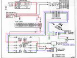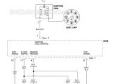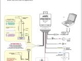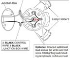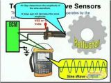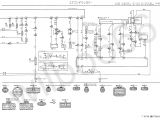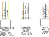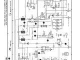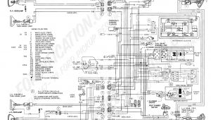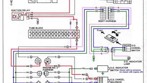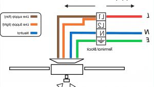
3 Wire Crank Sensor Wiring Diagram– wiring diagram is a simplified gratifying pictorial representation of an electrical circuit. It shows the components of the circuit as simplified shapes, and the faculty and signal connections in the midst of the devices.
A wiring diagram usually gives counsel nearly the relative tilt and understanding of devices and terminals on the devices, to incite in building or servicing the device. This is unlike a schematic diagram, where the harmony of the components’ interconnections on the diagram usually does not settle to the components’ innate locations in the curtains device. A pictorial diagram would con more detail of the visceral appearance, whereas a wiring diagram uses a more symbolic notation to make more noticeable interconnections exceeding inborn appearance.
A wiring diagram is often used to troubleshoot problems and to make sure that every the connections have been made and that whatever is present.
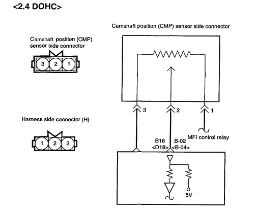
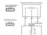
i have 04 kia optima 2 4l an the cam sensor plug with 3
Architectural wiring diagrams fake the approximate locations and interconnections of receptacles, lighting, and long-lasting electrical services in a building. Interconnecting wire routes may be shown approximately, where particular receptacles or fixtures must be on a common circuit.
Wiring diagrams use all right symbols for wiring devices, usually oscillate from those used on schematic diagrams. The electrical symbols not by yourself play a part where something is to be installed, but then what type of device is subconscious installed. For example, a surface ceiling lighthearted is shown by one symbol, a recessed ceiling spacious has a every other symbol, and a surface fluorescent vivacious has unorthodox symbol. Each type of switch has a interchange fable and hence attain the various outlets. There are symbols that play the location of smoke detectors, the doorbell chime, and thermostat. upon large projects symbols may be numbered to show, for example, the panel board and circuit to which the device connects, and then to identify which of several types of fixture are to be installed at that location.
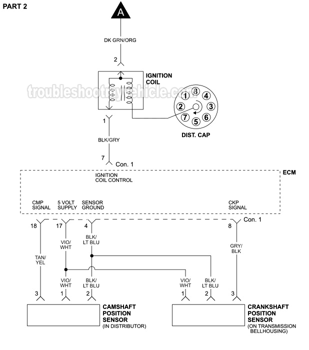
1997 dodge ram 1500 wiring harness diagram blog wiring diagram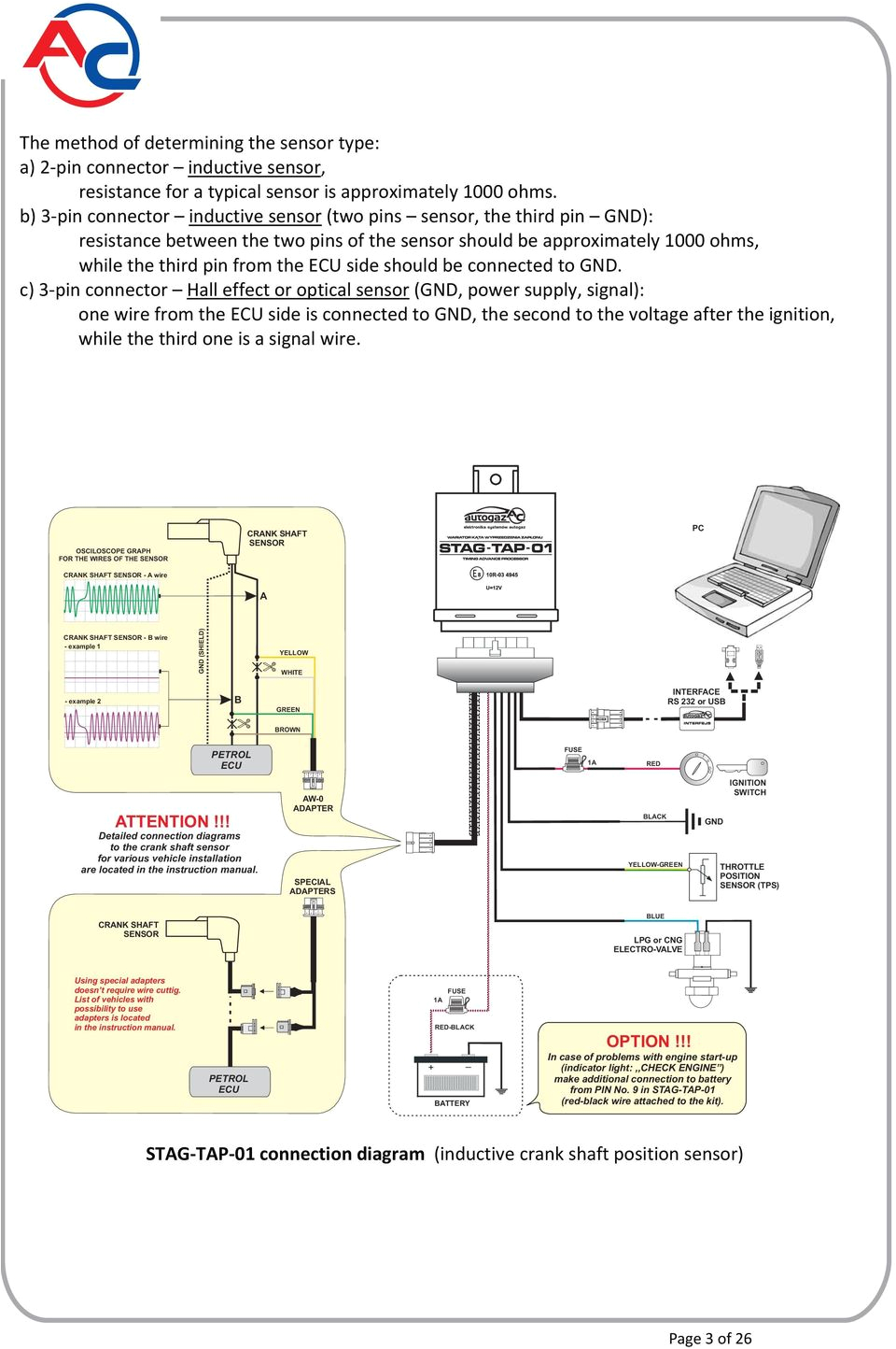
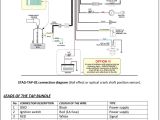
connection and programming instructions pdf free download
A set of wiring diagrams may be required by the electrical inspection authority to approve link of the habitat to the public electrical supply system.
Wiring diagrams will moreover attach panel schedules for circuit breaker panelboards, and riser diagrams for special services such as blaze alarm or closed circuit television or extra special services.
You Might Also Like :
- Cat C15 Acert Wiring Diagram
- 2001 Dodge Ram 1500 Headlight Wiring Diagram
- 50cc Scooter Cdi Wiring Diagram
3 wire crank sensor wiring diagram another image:
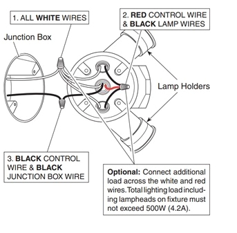
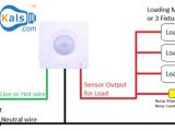
sensor operated light wiring diagram wiring diagram sheet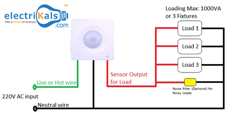
sensor operated light wiring diagram wiring diagram sheet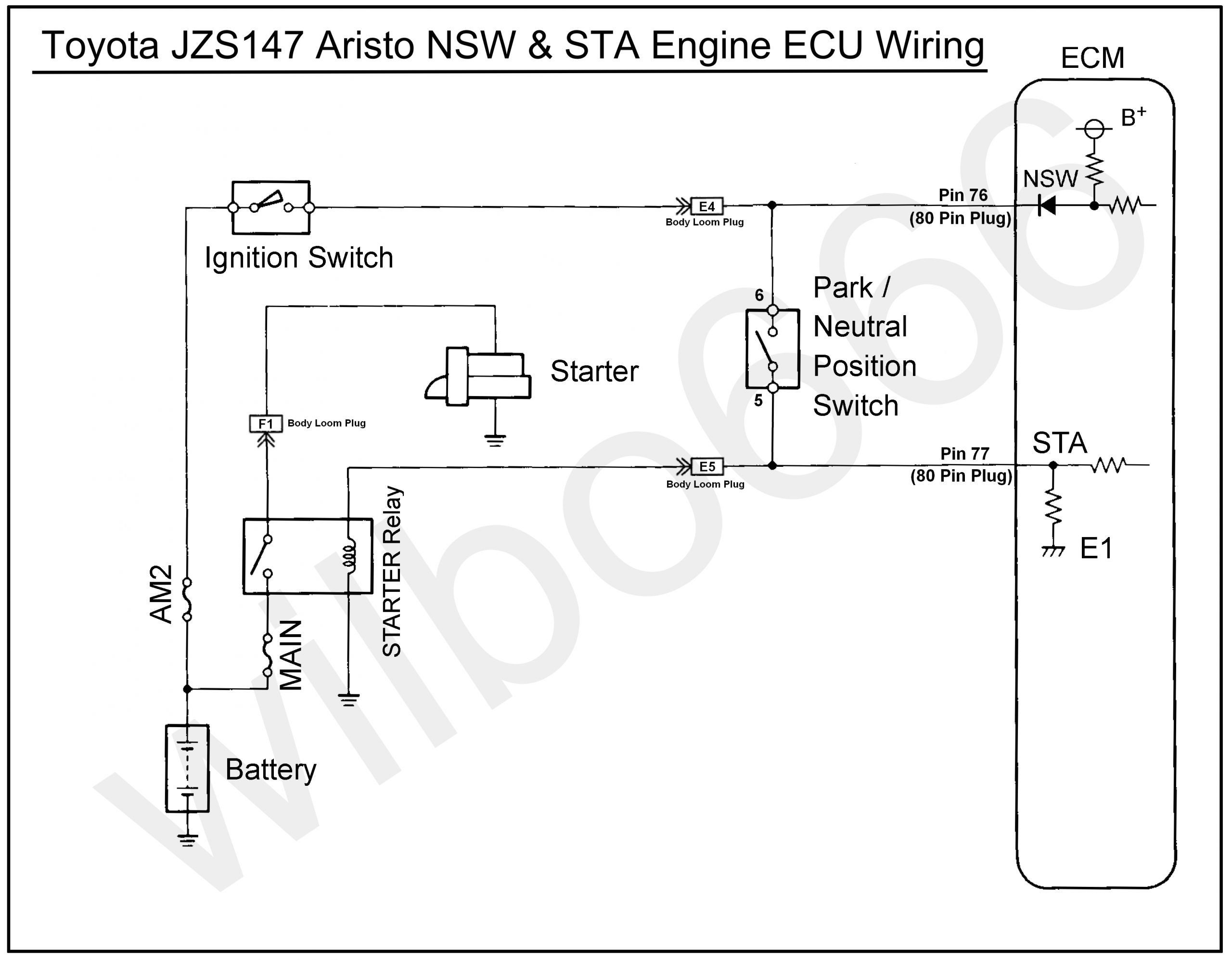
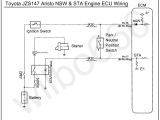
wilbo666 2jz gte jzs147 aristo engine wiring
three wire sensor three wire sensor in plc three wire sensor connection in plc cam and crk wiring diagrams this video is dedicated to cam and crk sensor testing and operational parameter but from an electrical and wiring diagram interpretation point of view the cam and crk sensors are types of speed how do i wire my 3 wire sensors automation insights three wire sensors are used in various applications from detecting parts to locating position of the actual machine they can come in all different technologies such as inductive photoelectric and capacitive just to list a few although the sensor technology may differ all 3 wire sensors are wired the same a three wire sensor has 3 wires present wiring question for xe crank sensor with 3 pin plug tech my crank sensor original vauxhall has a black 3 pin plug numbered 1 2 3 my wiring loom has two wires one white one black and they are contained with a shielded is this known as a shielded pair as you can tell i have no idea what im talking about so my question is how should i wire the crank cam angle sensor wiring shielded cable grounding hpa q a sensor wiring and shielding what s the go this question which has been taken from a free live motorsport wiring webinar asks for advice on crank and cam angle sensor wiring how to test a gm 3 wire crank sensor hall effect type there are two crank sensors on these early gm 3100 engines one is a 2 wire magnetic type sensor that gm calls a 7x crank sensor 7 pulses per 360 degrees of crank rotation the second is a 3 crankshaft position sensor wire how to splice wires together in your car duration 3 cam and crk wiring diagrams duration 5 16 adptraining 574 529 views 5 16 check engine light and the cam sensor autozone car wires pulled out of crank position sensor looking for wires pulled out of crank position sensor looking for wiring diag for reinstalling 2000 5 3 p u hellocustomerand welcome to just answer here is the wiring diagram for the 5 0 and 5 7 liter engines if you feel my answer was helpful please click on accept feedback bonuses are always welcome crankshaft position ckp sensor connector connector part information 12059595 3f m crank sensor quick fix crank sensor quick fix there are two types of crank sensors and two types of tests the 2 and 3 wire sensors here are the flash points for the crank sensor testing starting system wiring diagram learn to navigate this system s wiring circuitry and diagram using current flow analysis relay and module operation and neutral switch actuation such as circuit completion see how the anti
