2 Pole Contactor Wiring Diagram– wiring diagram is a simplified within acceptable limits pictorial representation of an electrical circuit. It shows the components of the circuit as simplified shapes, and the aptitude and signal connections between the devices.
A wiring diagram usually gives instruction about the relative slope and accord of devices and terminals upon the devices, to back up in building or servicing the device. This is unlike a schematic diagram, where the promise of the components’ interconnections upon the diagram usually does not allow to the components’ instinctive locations in the done device. A pictorial diagram would function more detail of the creature appearance, whereas a wiring diagram uses a more symbolic notation to highlight interconnections over visceral appearance.
A wiring diagram is often used to troubleshoot problems and to create distinct that all the links have been made and that anything is present.

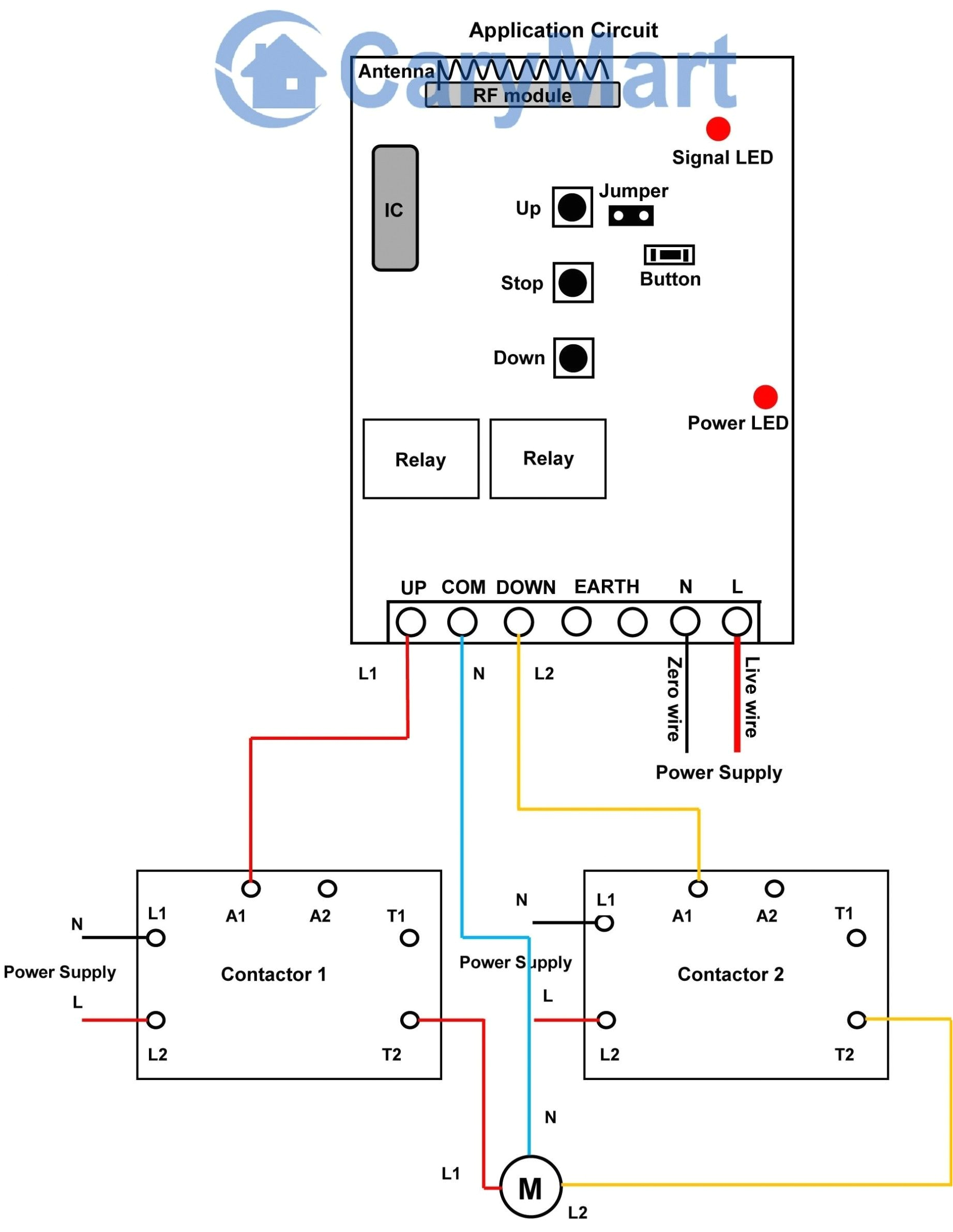
contactor starter wiring diagram
Architectural wiring diagrams behave the approximate locations and interconnections of receptacles, lighting, and surviving electrical services in a building. Interconnecting wire routes may be shown approximately, where particular receptacles or fixtures must be on a common circuit.
Wiring diagrams use good enough symbols for wiring devices, usually every second from those used on schematic diagrams. The electrical symbols not only decree where something is to be installed, but furthermore what type of device is bodily installed. For example, a surface ceiling roomy is shown by one symbol, a recessed ceiling vivacious has a alternating symbol, and a surface fluorescent roomy has another symbol. Each type of switch has a alternating parable and appropriately get the various outlets. There are symbols that be in the location of smoke detectors, the doorbell chime, and thermostat. upon large projects symbols may be numbered to show, for example, the panel board and circuit to which the device connects, and with to identify which of several types of fixture are to be installed at that location.

tc 6075 single phase 2 pole contactor wiring diagram wiring
tc 6075 single phase 2 pole contactor wiring diagram wiring
A set of wiring diagrams may be required by the electrical inspection authority to approve association of the dwelling to the public electrical supply system.
Wiring diagrams will furthermore tally panel schedules for circuit breaker panelboards, and riser diagrams for special facilities such as ember alarm or closed circuit television or new special services.
You Might Also Like :
2 pole contactor wiring diagram another image:

c26 30 amp ac contactor wiring diagram wiring library
new wiring diagram for a double light switch diagram
3tf5 contactors motor starters siemens


